(Horn (2005) PNAS 102, 4929-4930)
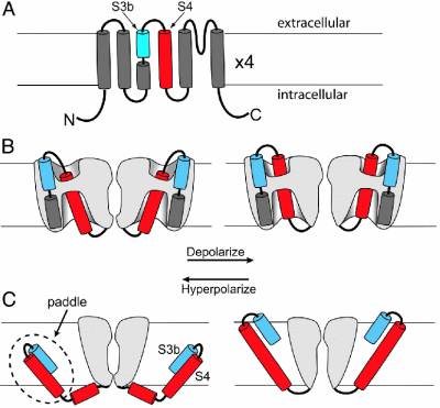
Models of topology and voltage sensor movement: The membrane is indicated by horizontal lines. (A) Topology of a potassium channel subunit
with six transmembrane segments (S1-S6). (B) Conventional model of voltage sensor
movement. Gray represents protein. Depolarization (right) moves the extracellular portion
of the S4 segment (red) outward through a short hydrophobic gating pore, opening the
permeation pathway. Most of the S4 segment is surrounded by hydrophilic vestibules. The
transmembrane electric field falls mainly across the gating pore. (C) Paddle model.
Two opposing subunits are shown. Depolarization moves the paddle outward through the lipid,
pulling the cytoplasmic activation gate option. The transmembrane electric field felt by S4
arginines falls mainly across the lipid.
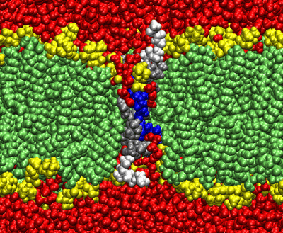
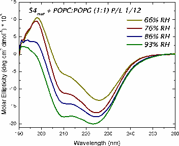
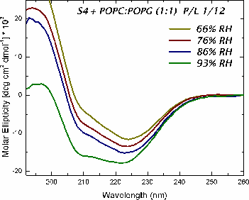
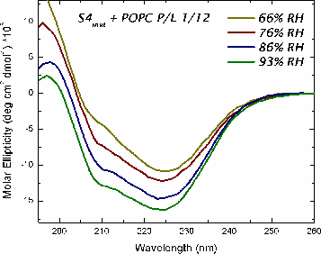
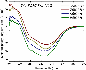
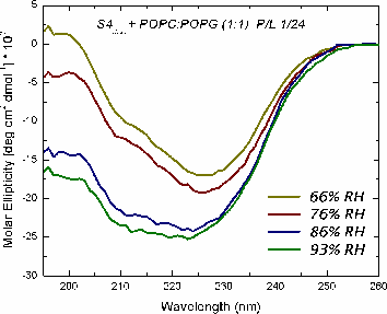
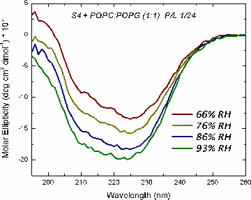
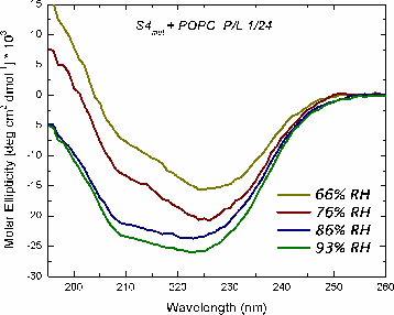
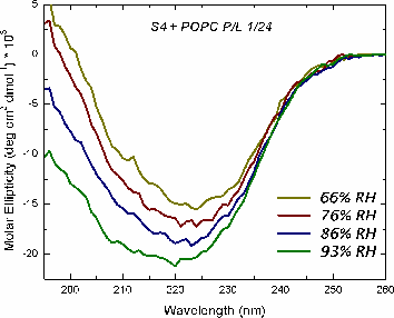
The mechanism of voltage-gating in K+ is controversial. The source of the controversy resides in the idea that the paddle model [Jiang et al. Nature (2003) 423:42-48] is implausible because of the energetic cost of burying charges in a lipid bilayer. Hessa et al. [Science (2005) 307:1427] reported that ΔG ≈ 0 for transmembrane insertion of a K+-channel S4 helix into the endoplasmic reticulum (ER) membrane. They concluded that S4 is distributed between two states: secreted and transmembrane. A mutant (S4mut) with two arginines shifted toward the C-terminus inserted even better into the ER. Molecular Dynamics simulations of the S4 helix of Hessa et al. inserted across the membrane [Freites et al., PNAS (2005) 102:15059] show it as stable across the bilayer, because water and lipid phosphate groups form an H-bonded network around the membrane-buried arginines. These findings suggest that the paddle model is not consistent with the high charge content. Here, we have used two synthetic model peptides, S4 and S4mut, to study its interaction with lipid bilayers. Spontaneous insertion of a helix into a preformed LUV bilayer may require surmounting a high energy barrier separating interfacial and transmembrane conformations. Therefore, we co-lyophilized the peptide and the lipid in alcohol and used oriented circular dichroism to study insertion. We found two S4 helix populations distributed between transbilayer and surface orientations. But S4mut adopts a predominantly transbilayer orientation in hydrated lipid multilayers formed by POPC:POPG (1:1). The insertion is hydration-dependent. This shows that the insertion of both peptides across the LUV bilayer is thermodynamically possible. Additional studies will provide us with better insight into the behavior of these peptides in membranes.
Recent work supports the idea of a transmembrane S4:
From these findings, we synthesized both peptides (S4 and S4mut) and
studied their orientation in the lipid membrane by means of oriented circular
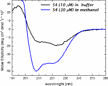
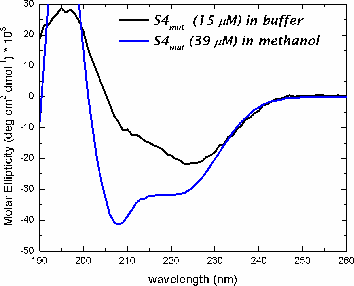
dichroism (OCD). The peptides used were:
S4: GGPG-LGLFRLVRLLRFLRILLII-GPGGW
S4mut: GGPG-LGLFRLVRLLFRLIRLLII-GPGGW
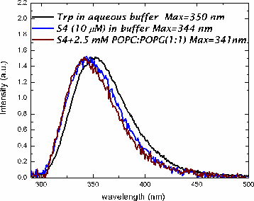
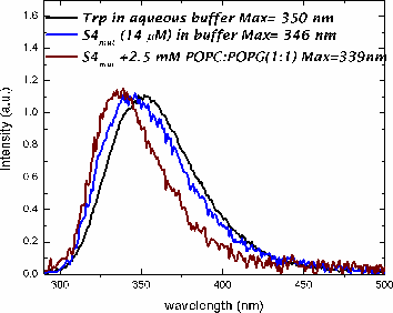
In methanol, both peptides adopt a helical conformation. In buffer, both peptides are in an aggregated state, based upon light scattering and fluorescence measurments.
|
|
|
|
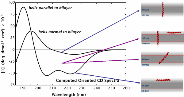
Oriented CD is used to distinguish the orientation of the peptide in the lipid membrane [Wu et al., (1990) Biophys. J. 57:797]. Computed oriented CD spectra for two extreme cases: 1) transmembrane peptide population, and 2) interfacial peptide population. Any combination of the two spectra may indicate a mixture of transmembrane and interfacial populations, or that the peptide is tilted in the membrane. These two can't be distinguished by this technique.
|
|
|
|
|
|
|
|
This work was supported by NIH grants GM 46823 and GM 069783 and RR14812.